Portal
Engines
Portal
engines are great for rendering inside environments, since they are based on the
notion of only rendering areas that can be seen through openings (portals). The
shape of the visible area changes as it passes through each portal and eventually
fails to see any more portals, at which point the algorithm stops. With a little
algebraic trickery, a portal can also double as a mirror.
Here's
an example:
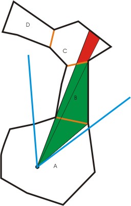
The
viewpoint is in room A, with the viewport frustum defined as the two blue lines.
The orange lines represent portals. The viewport frustum can see the portal leading
to room B, so it reduces the frustum to the green area and looks for visible portals
in Room B. It sees one at the far end and reduces the frustum to the red area
and looks for visible portals in room C. It doesn't see any there, so it renders
room C, then B, then A. And we're done.
What
you need
In
order to get a portal algorithm going, you'll need to start with some guidelines
on how to define your environment:
- Vertices
for all your surfaces
- Surfaces
referring to the vertices (some vertices are shared between surfaces, so references
are used to avoid repeats). A surface can have an alpha blending value to make
it translucent, and can be flagged as a mirror surface (only for purposes of ignoring
its rendering... the corresponding portal mirror will handle that)
- Rooms
made up of multiple surfaces and multiple adjacent portals
- Portals
made up of the same vertices the surfaces refer to. Portals have a front room
and back room (mirrors only have a front room, and if a mirror is meant to have
an alpha surface, it should refer to the room surface it will use to render after
the mirror image is done rendering)
Surfaces
and portals should be defined in the same direction (clockwise or counterclockwise)
so that their normals are similar as well. Surface segments should have a unit
segment along their length, length of the segment itself, and a segment normal
that points into the surface to speed up some calculations.
It
is also possible to define two alpha blended surfaces to oppose each other - that
is, they make up a two-sided alpha surface. This is important for applying decals
that would be visible on each side, but that's another discussion. This isn't
an article about applying decals, it's for a portal engine. Just something to
keep in mind.
It
isn't necessary to define every room as convex (no pointy parts) if you're using
depth testing hardware, although the surfaces should be convex planes (for easy
submission to the rendering routines), and the portals MUST be (for generation
of valid frustums). So if you want a portal that is concave, compose it of adjacent
convex polygons, each a different portal.
Also,
if you plan to have any mirrors, make sure the algorithm tests mirrors in the
same room that would occlude others first (define them first in the adjacent portal
list for any given room).
It
would be wise to have texture mapping be as uniform as possible on the mirrors,
since it's likely they will be spliced by a frustum, and you'll need to be able
to calculate new texture coordinates for a nice render.
The
algorithm
In
basic terms, the algorithm goes like this:
Start
in the room where the viewpoint is, and a frustum defining the visible viewport.
- For
each portal adjacent to the room
- If
the portal is visible:
- Merge
current frustum with frustum that would be made between the viewpoint and the
portal. Get rid of extraneous frustum planes
- Do
a subparse into the room on the other side of the portal using the new frustum,
repeating this algorithm
- Render
the room
This
causes the room's contents to be rendered last in a back to front method. This
would allow you to use a painter's algorithm of you want to avoid any depth testing
at all, but that would only work if your rooms are defined as convex. If you have
any wall angles greater than 180 degrees, you better use depth testing.
Incorporating
mirrors, the algorithm turns into this:
Start
in the room where the viewpoint is, and a frustum defining the visible viewport.
- For
each mirror portal adjacent to (in) the room
- If
the mirror portal is visible:
- Make
a new frustum by merging the current frustum with frustum that would be made between
the viewpoint and the mirror. Get rid of extraneous frustum planes
- Stencil
the mirror surface exactly as it is visible in the new frustum (requires polygonal
splicing using the new frustum - old frustum would work just find to splice as
well, mathematically you should get similar results). Use depth testing, but don't
write color or depth. Store the spliced polygon, we'll use it later.
- Set
the clip plane to the mirror's surface so nothing renders past it
- Flip
the frustum on the mirror portal's plane
- Push
the rendering transformation on the stack
- Flip
the rendering transformation on the mirror portal's plane
- Toggle
the front face of polygons for culling (clockwise polygons will now be counterclockwise)
- Do
a subparse into this same room using the new frustum, repeating this algorithm,
rendering only to the allowed stencil value on the mirror surface
- Toggle
back the front face for culling
- Pop
the rendering transformation from the stack
- Depth
mask the stored spliced mirror surface if it has no associated room surface to
render (no color writing, just depth writing), or render the room's stored spliced
alpha surface (requires preparing a new surface with recalculated texture coordinates),
writing to the depth buffer
- Restore
the clip plane to its previous state
- Restore
the stencil on the mirror surface to its previous state
- For
each non-mirror portal adjacent to the room
- If
the portal is visible in the current frustum:
- Make
a new frustum by merging the current frustum with frustum that would be made between
the viewpoint and the portal. Get rid of extraneous frustum planes
- Do
a subparse into the room on the other side of the portal using the new frustum,
repeating this algorithm
- Render
the room, ignoring surfaces flagged as a mirror
As
you can see, there is a lot of preparation for rendering mirrored surfaces. A
stencil is required so that the mirror's image doesn't cut into the viewport's
depth buffer outside of the mirror's visible bounds. The clip plane keeps geometry
from reaching out of the mirror itself. The depth masking of the mirror surface
afterwards prevents anything else from cutting into the rendered mirror image.
It is important for mirror surfaces to be parsed and rendered first, front to
back, to avoid corruption of their images by future rendering (including mirrors
encountered deeper in the parse). Also note that only one active clip plane is
necessary, since you can store and restore clip planes as each mirror parse completes.
Now
for a little discussion:
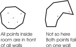
- Frustums
are made up of a viewpoint and multiple planar normals. Points are visible in
a given frustum if they are in front of all the normals of the planes that make
up the frustum: (point minus viewpoint) dotproduct with plane normal > 0
- Portals
are visible as long as they face the viewpoint in the room we are currently parsing
(if we are in the front room, the dotproduct with the normal must be positive,
otherwise it must be negative) and if any of their points are visible, any of
their segments strike a frustum plane at a point that is visible to all the other
frustum planes, or an intersection between two frustum planes that is visible
to all the others strikes the portal inside its bounds (this case is needed for
a portal that we are so close to that no points or segments are visible). Note
that this doesn't cover all cases. It's still possible for a frustum to exactly
intersect a portal on just segments and points, causing a floating truncation
problem for accuracy. This is discussed in a section below. Special case: If we
are exactly on a portal plane (dotproduct = 0), it should be visible from both
sides. Make sure you put in a check, however, to not parse into a room you just
came from, so you don't get an infinite loop or stack overflow. There are other
ways to determine portal visibility that floating truncation doesn't create such
a problem for (see below).
- When
merging a frustum with a portal to make a new frustum, the original frustum's
plane is extraneous (not needed) if all the portal's points are visible to it.
Otherwise, include the plane. A portal's segment should be added as a frustum
plane (cross product the segment with the offset of either point to the viewpoint)
if either point is visible in the old frustum, or the segment intersects an old
frustum plane that is visible to all the other old planes. This may not get rid
of all extraneous planes, but it's close. It does, however, guarantee that we
have enough planes to properly exclude future portals. Beware that you must make
sure the normal for any new plane faces into the frustum, the calculation of which
is affected by which side of the portal you are on (front or back). As a final
note, it's better to have too many planes in the new frustum than too few. You
could freely just take the old frustum and add all the portal segments as planes
and get a valid one. It's best to have as few as possible, though, to reduce future
calculations.
- You
should only allow a certain depth for parsing mirrors so you don't get an infinite
loop or stack overflow in a hall of mirrors. I assigned 8, but even a room with
3 adjacent mirrors (two walls and the floor) can bring things to a crawl.
- When
used with hardware acceleration, you can mostly avoid having to accurately frustum-splice
the polygons you render and just depend on the depth buffer to occlude everything.
The one exception is mirror surfaces, which must be accurately stenciled with
a splice. One reason why is discussed in a test case at the bottom. If you were
to write a polygon splice routine to handle every polygon you render, then you
probably won't even need depth buffering or stenciling for anything. But you will
still need a clip plane on the mirror surfaces so that geometry doesn't poke out
of it.
- Regarding
stenciling: I keep track of my current mirror depth, starting at 0. The stencil
buffer itself also starts at 0. When I encounter a mirror, I perform a stencil
increment on the spliced mirror surface, raising the values to 1. If I encounter
another mirror inside that one, that mirror's spliced surface only renders to
stencil 1 and increments them to 2, etc. After the mirror is done, the stencil
is decremented from 2 to 1, and from 1 to 0 to restore the stencil as mentioned
in the algorithm.
As
a final note, since it's possible for a room to be parsed more than once during
rendering (imagine a long hallway with multiple doorways, and you are in a long
room looking at two of those doorways), you should ensure that each room is only
rendered once and in the proper order. I keep a list of room ID's and keep track
of the very last room I parsed from. When it's time to render the room according
to the algorithm, I just add that room's ID directly after the last room's ID
in the list (if it isn't already there). Then, when all parsing is done, I just
render the rooms from the end of the list to the front. This way, it's a true
back to front render with single room draws, even if I've parsed a room twice.
Portal
visibility challenges
I
listed some generalized cases that imply portal visibility in the algorithm discussion
above, but there is one case that floating point truncation fails to address:
If a portal's points and segments are such that they coincide exactly with a frustum's
plane intersections, the calculations may fail to yield an accurate result. There
are at least two possibilities of getting around this problem, but they can be
computationally expensive (at least, the first one is, the second one might actually
save you some processing):
- If
you submit the portal's polygon to be spliced by the frustum and get a non-null
result, you know the the portal is visible. Actually, if you test for all the
points to be inside first and all of those fail, then you can attempt the splice
and avoid testing the segment intersections. So, in some cases, this is actually
faster. I do this now (although I have yet to pass the resulting splice to the
mirror preparation code, since I don't always enter that portion of code to determine
visibility). This would be slow with portals that have a lot of vertices and frustums
with a lot of planes.
- If
you have perfected the frustum merge routine to remove absolutely all extraneous
planes, perform a merge with the portal, and get a non-null result, the portal
is visible (AND you have already done the frustum merge, so you have that result
now, too.). It might be worth pursuing this option, even though determining that
a portal that isn't visible through other means may sometimes be faster.
Splicing
a polygon with a frustum
This
isn't the fastest way for certain, but it works.
Prepare
an array of vertices and pass it to the splicer. Also provide a planar normal
and a point on that plane. The routine returns a new array of points that make
up the spliced polygon (It keeps all the points in front, and adds a single exit
and entry point for the group of vertices that are in back, if any). Repeat for
every plane in the frustum, and your end result is the spliced polygon. Watch
for 0 vertices being returned, signifying a null result.
This
routine could be written better to avoid passing back arrays of points repeatedly
(in other words, make it a single pass routine), but you'd somehow have to ensure
that your planes are adjacent to each other in the frustum, and that none are
extraneous. That way you could follow the planes and polygon around and splice
up the polygon in one pass. I'm holding off on writing that algorithm myself.
I wrote a one-pass polygon-polygon intersection routine for applying decals to
surfaces and got severely burnt out on that kind of logic.
As
has been mentioned, you could pass a portal to this routine to determine if the
portal is visible to that frustum. A null result means the portal isn't visible.
Some
test cases
Here
are some maps that might be useful to set up to make sure your portal engine is
doing what it's supposed to. Note that if you have written a total polygon splice
routine and use it for all rendering, you likely won't run into many of the problems
discussed here.
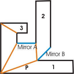
If
you are at point P looking at Mirror A, you shouldn't see hallway 3 cutting into
mirror A's rendered image (avoided by depth masking mirror A's surface after rendering
it), and you shouldn't see mirror A's image of hallway 1 cutting into hallway
2 (avoided by stenciling mirror A's surface properly). Mirror B is there just
for mirror-mirror testing.
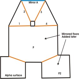
I
originally made this map to test that mirror A's alpha surface wouldn't be rendered
more than once when viewed from point P (its room is parsed twice by passing from
the room with point P through portals 1 and 2, then 3 and 4, which causes the
mirror's image and surface to be rendered twice by the algorithm - but proper
stenciling of the mirror via the frustums avoided accumulation of the alpha surface).
I also wanted to make sure the alpha surface at the lower left didn't accumulate
(my algorithm only renders rooms once even though they may be parsed multiple
times, which the alpha surface's room could be because of the post slicing the
view down the middle).
After
I added the two mirrored floors, however, I ran into some other problems. Suddenly,
mirror A was sometimes being rendered multiple times, and it turned out that the
frustums I was preparing as I passed through mirror portals were incomplete due
to floating point truncations, causing slight failures that should have been successes.
So, I allowed some tolerance in the frustum merging routine, and it took care
of the problem. This tolerance might allow more planes in the frustum than I need,
but at least that isn't a destructive result. It just results in extra superfluous
planes to calculate against deeper into the algorithm.
Another
problem I had after adding the mirrored floors was that portions of some mirrored
surfaces would simply fail to render. I believe this was related to frustum planes
that were almost coincident with the points and segments of a portal, which caused
accuracy problems with the portal visibility algorithm. I tried adding some tolerance
to that routine, but it didn't totally fix the problem, and created others (for
some strange reason, some mirrors would render their images but failed to render
the alpha surface on the mirror itself). It mostly happened from point P2 while
near the floor looking into the main room. I altered the code to test for visibility
by testing all the vertices, and if all those fail, just submit the portal for
splicing. If I get a non-null result, the portal is visible. I set a control in
my code to activate that test when I could see the first test failing, and the
new code fixed it.
Other
test ideas
In
my code, I actually set an initial frustum to be very narrow and rendered an alpha
quad that represented its bounds in the viewport to see the result when it intersects
portals. It was a handy way to troubleshoot specific cases. When dealing with
mirrors, it was be interesting to see how everything within a mirror was rendered
but everything outside the quad on the mirror will be blank, and random other
pieces of geometry outside the quad will be seen from rooms that were rendered
unstenciled.
Avoiding
artifacting
For
the most part, if you're using hardware acceleration and aren't splicing every
polygon with frustums for rendering, the only time you'll have to worry about
artifacting is with mirrors. And so far, what I've seen is slight. If you want
to see how bad it can get for you, set up a room with a square post in the center,
and 4 rooms and portals around it. Then move around the room and see if you're
satisfied with the results.
By
using the same vertex values for adjacent surface segments, you avoid most artifacting
problems. However, mirrors present a new problem. If the flip on the mirror plane
isn't exact (nothing is exact in computers), there may be some artifacting on
the edges of the mirror surface. It will be very noticable if you clear the screen
to a noticable color before you beging your rendering. I like 128,128,128 gray
myself. The dots still appear here and there, but they aren't horribly obvious.
That might change in a very dark room, though. I recently changed the value to
0,0,0 black to avoid gray dots appearing in the darkness.
Another
problem I ran into originally was Z fighting on the alpha surfaces of mirrors,
because I was rendering those surfaces with the room walls after depth masking
the mirror surface. After I coded to have the mirror parse routine render its
depth mask and alpha surface at the same time, I avoided having to solve that
problem (originally I tried receding the depth mask a little inside the mirror,
but then it was visible around hard corners. The way I finally solved it is more
complete).
One
tweak I do perform to reduce artifacting with mirrors is recede the viewpoint
slightly when I flip it. The rendered image inside might foward by a minute amount,
but it's something.
One
theory about artifacting I have yet to fully explore is the idea of same input,
same output. I figure if I can guarantee that all segments and vectors are heading
in the same direction (x always positive, if x = 0 then y is always positive,
if y = 0 then z is always positive, reverse the vector to accomplish this), maybe
I can make sure they always generate similar results. To further enforce it, I
would hold on to spliced segments for use at the end of a routine, but the source
segment would be retained and used in all calculations where that segment is involved.
That way, there aren't any second, third, or greater generation truncations on
the same segment occurring. But, that's a bit off, and I don't even know if it
will work. Still, a room with many adjacent mirrored surfaces sharing many segments
might be a good test.
The
main places where this kind of control would be needed is in polygon splicing,
frustum merging, and in whatever way it can apply, flipping the rendering transformation.
Polygon
splicing is always done with a frustum and an original surface. The frustum planes
only come from the original viewport frustum and plane made from original portal
segments. So it seems the only place where second generation truncation could
occur is in the polygon splice routine. The same segment could be spliced multiple
times by different planes. Using the original segment for calculation of all splices
would keep the truncation at a minimum instead of letting it get worse.
Frustum
merging is just a matter of keeping or getting rid of planes that came from original
sources, so assuming the originals are accurate, this shouldn't be an issue. The
directions of vectors used to generate planar normals could be controlled.
Ensuring
that flipping the rendering transformation is accurate could be as simple as using
double floats instead of singles. Multiple flips could occur, so perhaps it would
be prudent to hold on to those values and pass them on.
Also
make sure you push and pop values or copy them from storage rather than "calculate
them back". As an example, I ran into a situation where I spliced a mirror
and prepared a stencil, but tried to restore the stencil by rendering the original
surface rather than the splice. I got intermittent pixels that didn't unstencil.
Restoring the stencil by using the splice fixed the problem.
Funky
mirrors
If
you don't do mirrors right, you can really get some strange results.
- If
you don't stencil, you get mirror images cutting into the "real" world,
including the object representing you.
- If
you don't depth mask a mirror's surface after rendering it, future geometry can
cut into the mirror's image from behind
I
previously thought that it was ok to have multiple mirrors in the same room as
long as the mirrors are defined in order of occlusion. But there is one possibility
I recently considered. If you have two mirrors opposite each other and stand in
front of one, your position will flip in front of the other mirror for rendering.
And since the rendering of a mirror's image starts in the same room of the mirror
itself, the new viewpoint will see the mirror on the other side and work with
that. I can't testify that strange effects occur when this happens, since in my
demo, I haven't seen anything strange happen as a result. But I can testify that
the opposite mirror's portal was calculated as visible and caused another unnecessary
(and realistically impossible) render. So, for safe keeping, if your mirrors are
facing away from each other (facing opposite directions), you should probably
split the room with a portal and define them as being in different rooms. Mirrors
facing each other is fine, as long as they aren't more than 90 degrees off.
Another
test
Just
to make sure your portal evaluations, recursive logic and frustum mergings work
correctly, here's another test map:
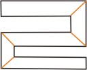
All
angles are 90 degrees on the walls, and the portals are exactly 45 degrees. In
order for this map to provide a test, you'll need collision detection. Slide into
a corner so that you are lying exactly on a portal and make sure everything renders
correctly (and you don't get an infinite loop).
Do
rooms need to be convex?
It
helps for determining if a point is inside a room by testing its position against
the surface normals. A concave room could calculate a point being outside the
room (see below). If you are rendering particles per room, then this becomes important
- particles rendered per room are rendered more accurately with alpha walls, since
they are supposed to be rendered first, then have the alpha wall blended over
them. It's also important when you need to calculate which room the viewpoint
is in to begin rendering, and you aren't determining the room you're in via a
BSP or other structure.
If
you have ways of calculating if a point is inside a room without using the surface
normals, then convex rooms may not be so necessary. It's up to the methods you
make available for yourself.
Note
that the portal rendering algorithm itself does not require convex rooms. Portal
visibility requires that you are on the correct side of the portal to see it,
and if the portal is around a corner in the same room, visibility fails. It's
just the initial calculation of which room the viewpoint is in that might require
it. If, however, your movement algorithm tracks passing through portals, you may
be able to determine which room the viewpoint is in without testing against surface
normals, assuming you can't pass through walls.
If
you find that the way you do things does require convex rooms, fortunately you
can always build convex rooms even if they are initially concave. Just splice
the room with portals until all the room sections and portals are convex, and
set it up that way.
Note
that even though the rooms may not need to be convex, the portals do for accurate
visibility and valid frustum merging. Mirrors especially should be convex, since
the algorithm has to splice up a polygon to stencil.
If
you are finding that your map designs are preventing you from making convex areas
without overcomplicating the room and portal definitions, you can define other
volumes meant to contain rooms and represent portals that stretch outside the
visible geometry that will be rendered, and just use the other volumes to determine
room containment and portal visibility. The visible geometry should properly occlude
the outer edges of the larger portal, as long as the defined visible geometry
for a room doesn't cross the portal's surface.
To
illustrate, say you have a cavern and a jagged exit at one end. Stalagmites might
be part of the visible geometry of the room, and the exit could be star-shaped.
Setting up everything to be convex would probably require a lot of overdefinition.
So define a large square portal to define the exit that extends into the surrounding
walls, and define a large oval shape to contain the cavern (it could even be a
cube, as long as no other rooms intersect).
What
about everything else in the level? (Particles, light sources, doors, other objects)
The
portal engine itself mostly is really only good for rendering the walls themselves.
Where room containment can be calculated, particle rendering can be incorporated
into it. But particles can be so numerous that calculating that they remain in
the room as they move can be costly, so be careful.
However,
light sources and objects can't be rendered purely by room containment, since
there is size to them. They could easily exist in a room that isn't visible, but
the object should still be visible (like a warrior holding a long lance poking
through a door), and a light source should still be affecting other visible walls
(a 40 foot radius light above the warrior should be lighting the wall inside the
door).
I
solve these kinds of problems using an octree. I keep track of which objects,
lightsources, etc. that are touching each cell, and when I render a room, I refer
to all the cells the room touches and render all the objects and use all the lightsources
also touching those cells. Most of it is overapproximation (a warrior with a lance
is treated like a huge cube, since it could have any orientation), but I'd rather
get too much than too little.
The
octree also assists with limiting collision detection parsing and faster calculation
of which room a point is in (I figure out which cell a point is in and test the
point against all the rooms touching that cell).
I
maintain lists at both the cell level and object/light source/door/room levels
and keep them updated in parallel as objects and light sources move. It works,
for now.
So,
to summarize, I've set up my portal engine as follows:
- The
portal engine is coded to figure out which rooms to render based on visibility
through portals.
- Particles
and particle emitters are animated and rendered per room - the emitters and particles
can move from room to room. If they aren't in a visible room, they aren't animated
or rendered (although emitters attached to moving objects are continually evaluated
to determine which room they are in). Emitters and particle sets are stored only
in rooms, and will be destroyed when the rooms are destroyed with the portal map.
- Objects,
doors and light sources are referred to in octree cells. If they aren't listed
in a cell at all, or aren't listed in a cell touching a visible room, they aren't
used or rendered. Doors are primarily listed at the portal level, and lights and
objects are listed at the map level, so that they will be destroyed when the portal
map is destroyed.